Installation
This page guides you through the installation of a Lorabridge bridge and gateway device. First, you need to ensure your Raspberry devices fulfill the Requirements. Then you can either use the mostly automated Ansible setup or perform the steps manually.
Requirements
Hardware
You can find the necessary hardware here
Software
You need to:
- install Raspberry Pi OS (Lite is fine)
- make sure to enable ssh and ensure the raspi is connected to the Internet
- Install docker and docker compose [manual setup]
- install
git(viasudo apt-get install git) [manual setup] - enable spi (via
sudo raspi-config nonint do_spi 0) [manual setup] - install
esptool.pyon the bridge via pip or binary
Info
The setup was tested with Raspberry Pi OS based on Debian 12 Bookworm.
You can flash the OS onto the sd card with e.g. Raspberry Pi Imager. It can also add wifi configuration or static IP addresses.
Ansible Setup
This setup method automates several steps of the installation process of bridge and gateways devices. You need to clone the setup github repository. The repository provides an ansible project for setting up LoRaBridge devices via ssh.
You need to prepare the Raspberry Pi devices as described in Requirements.
Clone Setup Repository
Download the code for the Ansible setup and switch inside the folder:
git clone https://github.com/lorabridge2/setup.git
cd setup
Ansible Controller Requirements
You need to install the requirements listed in following files inside the repository on the host running the setup:
apt-requirements.txtPipfilerequirements.yml
Debian based distros
Install requirements via script
./requirements.sh
Manual installation
Install requirements manually with e.g.
xargs apt install -y < apt-requirements.txt
# apt-get install $(cat apt-requirements.txt | tr '\n' ' ')
pipenv install
ansible-galaxy install -r requirements.yml
Inventory file
Copy the inventory.sample file, name it inventory and Replace the placeholders with the actual values of the bridge and gateway devices.
[bridges]
<bridges ip address> hostname=<desired hostname>

[gateways]
<gateway ip address> hostname=<desired hostname>
Identifying devices
First, get the IP addresses of the devices e.g. via checking your router, dhcp server or configuring static IPs using the Raspberry Pi Imager.
To identify which device is the gateway or the bridge, establish a ssh connection and check the devices in /dev. Using the default hardware setup described in Hardware, only the bridge has a /dev/ttyUSB0 and a /dev/ttyACM0 device.
Configuration Variables
Configuration variables are defined in following places:
group_vars/all/all.yaml
group_vars/bridges/*
group_ars/gateways/*
roles/<role name>/defaults/main.yaml
You can overwrite them by creating a new yaml file (e.g. myconfig.yaml) inside group_vars/all/, group_vars/bridges/ or group_vars/gateway/ and configuring the desired value in there.
Doing this inside group_vars/all/ affects all devices, group_vars/bridges/ affects only bridge devices and group_vars/gateways/ affects only gateway devices.
Usually you will not need to change the configuration unless you changed the default user name.
Example for changing the user name to user1
- Create a custom configuration file
group_vars/all/custom.yaml - Insert the following content:
---
pi_user: "user1"
Executing the setup
Start the setup with the following command:
ansible-playbook -i inventory lorabridge.yaml --ask-become-pass --ask-pass
Manual Setup
Preparation of bridge unit
Step 1 - Cloning
Clone our top-level repository lorabridge2/lorabridge either via ssh per
git clone --recursive git@github.com:lorabridge2/lorabridge.git
or via https per
git clone --recursive https://github.com/lorabridge2/lorabridge.git
Info
You can also use the new github cli tool gh repo clone lorabridge2/lorabridge -- --recursive (prior config necessary - see manual)
Step 2 - Navigation
Navigate into the repository with cd lorabridge.
Step 3a - Config via Script
Execute ./create_env.sh which will create the necessary environment variables (.env files) for the bridge and the gateway. You need to copy the .env file of the other device (e.g. lorabridge/gateway/.env if you execute the script on the bridge) to the same location on the respective device.
Tip
You can use the scp command to copy the file
# inside the lorabridge directory
scp gateway/.env pi@<ip.of.gate.way>:/lb/path/lorabridge/gateway
Step 3b - Manual config
If you are setting up a bridge do cd bridge.
Copy env.example to .env and modify variables in .env as necessary, see config for further details.
Following variables need to be changed for a bridge device:
LORA_DEV_EUILORA_JOIN_EUILORA_DEV_KEYBASIC_AUTHGID_DOCKER
Info
variables are automatically substituted in docker-compose.yml file
Step 4 - Flash esp32 firmware
Execute ./prepare_esp.sh on the bridge to flash the firmware onto the esp32 device.
Step 5 - Container creation
Pre-built images
All images are pre-built via github actions on every commit and every sunday. Use those image with:
docker compose pull
docker compose up -d
Self-built images
You can build your own images for development purposes via:
docker compose -f docker-compose.dev.yml build --pull
docker compose -f docker-compose.dev.yml up -d
Preparation of gateway unit
Step 1 - Cloning
Clone our top-level repository lorabridge2/lorabridge either via ssh per
git clone --recursive git@github.com:lorabridge2/lorabridge.git
or via https per
git clone --recursive https://github.com/lorabridge2/lorabridge.git
Info
You can also use the new github cli tool gh repo clone lorabridge2/lorabridge -- --recursive (prior config necessary - see manual)
Step 2 - Navigation
Navigate into the repository with cd lorabridge.
Step 3a - Config via Script
If you already used create_env.sh on the bridge, then copy the lorabridge/gateway/.env file to the same location on your gateway. Otherwise follow the steps decribed here and then copy lorabridge/bridge/.env to your bridge instead.
Step 3b - Manual config
If you are setting up a gateway do cd gateway.
Copy env.example to .env and modify variables in .env as necessary, see config for further details.
Following variables need to be changed, when setting up a gateway:
CHIRPSTACK_DEV_EUICHIRPSTACK_DEV_KEYCHIRPSTACK_API_SECRETCHIRPSTACK_PASSWORDCHIRPSTACK_HASHCOUCHDB_PASSWORD
Info
variables are automatically substituted in docker-compose.yml file
Step 4 - Container creation
Pre-built images
All images are pre-built via github actions on every commit and every sunday. Use those image with:
docker compose pull
docker compose up -d
Self-built images
You can build your own images for development purposes via:
docker compose -f docker-compose.dev.yml build --pull
docker compose -f docker-compose.dev.yml up -d
Adding another bridge device to the gateway
Device setup
Follow the instructions for setting up a bridge for the additional bridge.
When copying env.example to .env and modifying the default values, choose a unique identifier for LORA_DEV_EUI (has to be unique for every bridge).
Info
LORA_DEV_KEY needs to be the same as on the gateway.
Add device to gateway
Open the ChirpStack webinterface inside the browser via http://<ip-or-hostname>:8080.
Go to Applications and press on the name of the application LoRaBridge_DataPipe.
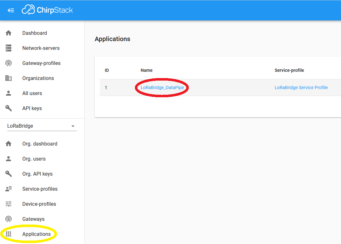
On the next page (Devices) press on Create.
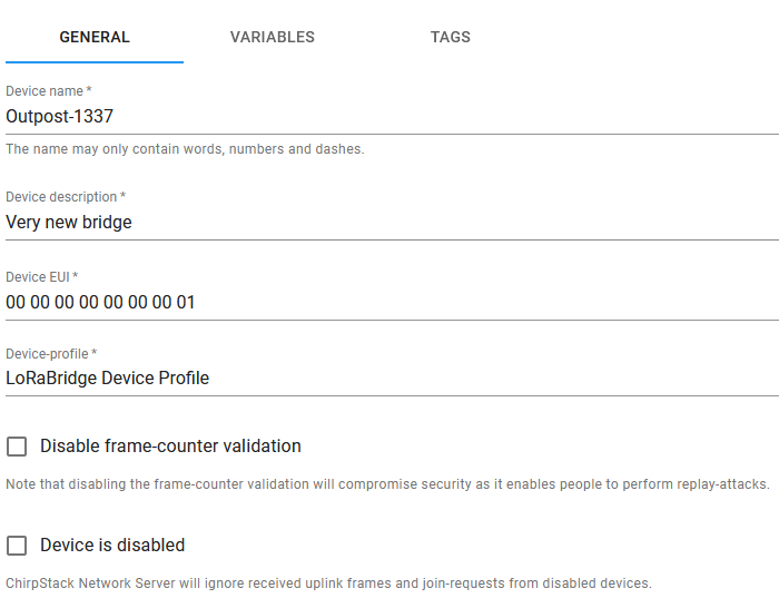
Fill in the device name and description, enter the new bridges' LORA_DEV_EUI in the Device EUI field and choose the LoRaBridge Device Profile as Device-profile. Then press on Create Device.
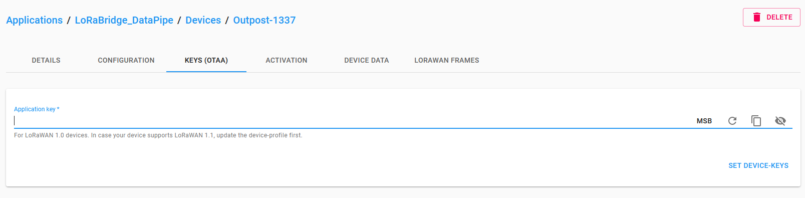
The webinterface redirects you to the page of your new device, the current tab should now be KEYS (OTAA). Enter the LORA_DEV_KEY value of your .env file in the Application key field and press SET DEVICE-KEYS.
Your device should now be up and running. It might take a while until device has connected to the gateway and sends packets.
Verify system functionality
For testing the system functionality the first time, it is useful to connect the both bridge and the gateway raspberry PIs e.g. into a local LAN network. This way, you can monitor more closely the behaviour of the both units and if necessary, perform some fine tuning.
As both units are up and running, pair a sensor with the bridge unit following the instructions here.
After the sensor transmits data (either after waiting or manually triggering it), the data should show up in the Home Assistant interface as shown here. Finally, configure a simple automation via LoRaMation and deploy it to the Bridge. After deployment, verify the creation of a corresponding NodeRED flow at (bridge IP address):1880.